GlowSense: Project Development
Initial Idea
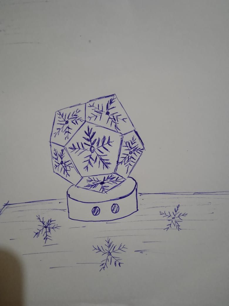
For my final project, I proposed an ultrasonic distance sensor lamp. The idea was to incorporate proximity sensing, not just to enhance the aesthetic appeal, but also to promote energy efficiency. I started with an initial sketch where the lamp’s shape was a dodecahedron, with snowflake patterns cut out on its faces to create interesting light patterns. The ultrasonic sensor would detect nearby objects, causing the lamp to glow when something is within a preset range and gradually increase to full brightness as the object gets closer.
.jpg)
Features
- Proximity-Based Dimming
- Automatic Lamp Control
- Energy efficient
Why a lamp ?
I came up with the idea for this mood lamp because I’ve always wanted one—not just for how it looks, but because I used to be afraid of the dark. Instead of a regular lamp that just turns on or off, I wanted something more interactive and comforting. By adding a distance sensor, the lamp responds to people nearby. It can light up when someone approaches or dim when no one is around. That simple reaction makes it feel more alive and personal. It’s meant to be soothing, especially for people like me who feel uneasy in the dark, but it could also appeal to anyone who enjoys cozy, ambient lighting.
Final Idea
As the classes progressed, I kept thinking of new features to add to my lamp. During a peer review, I got suggestions fromAkash and Namita about incorporating kinematics, which got me thinking about making the lamp’s movements more dynamic. Our instructor,Saheen , also pointed out the possibilities of adding wireless communication. Taking all of this into account, I came up with an updated version of my lamp that includes these ideas and makes it more interactive and responsive.
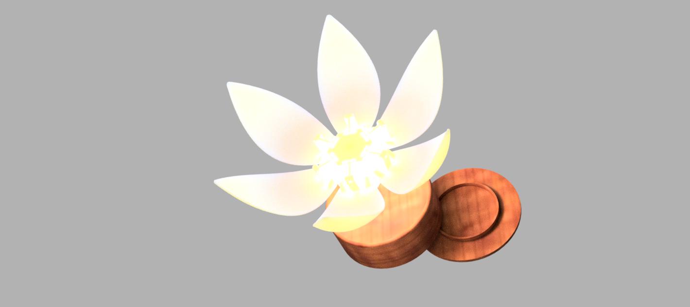
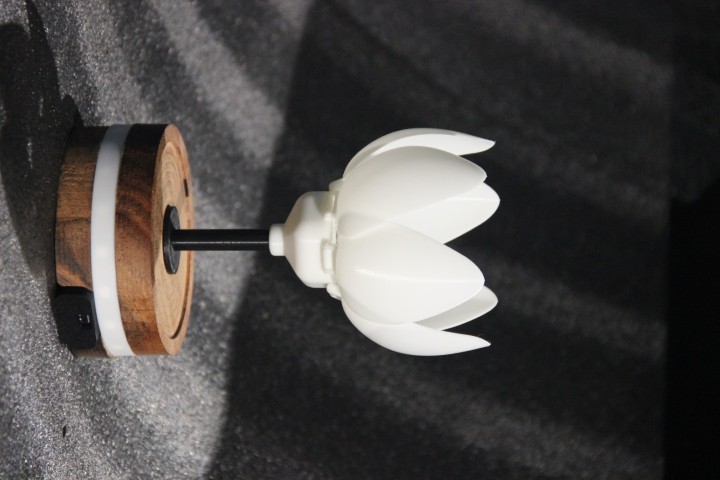
The final project consists of two blooming flower lamps that interact wirelessly. Each lamp features NeoPixels, allowing users to select custom colors through the GLOWSENSE app for a personalized lighting experience. Servo motors create a blooming effect, adding a lifelike, dynamic element to the design. A time-of-flight (ToF) sensor detects the distance of nearby objects, controlling the light intensity—glowing softly when the object is farther away and brightening as it gets closer. When someone approaches one lamp, the other responds wirelessly by blooming and glowing in sync. This interaction builds a sense of connection between the lamps, making them feel alive and emotionally engaging, even when placed apart.
What tasks have been completed ?
ELECTRONICS
After input week, I planned to add a display to show time to my final project. In output week I tried working with display and 12 V led strip which varies intensity with the input from distance sensor.
I also noted the variation in power supply current with respect to proximity
I wanted to test servo to learn how it works. I refered Noel Saji's Output devices week. Then I understood that my current mechanism will not support the up and down motion for blooming of the lamp. So I needed to redesign the mechanism.
I tested the Kodular app in interface and application programming week.
MECHANISM
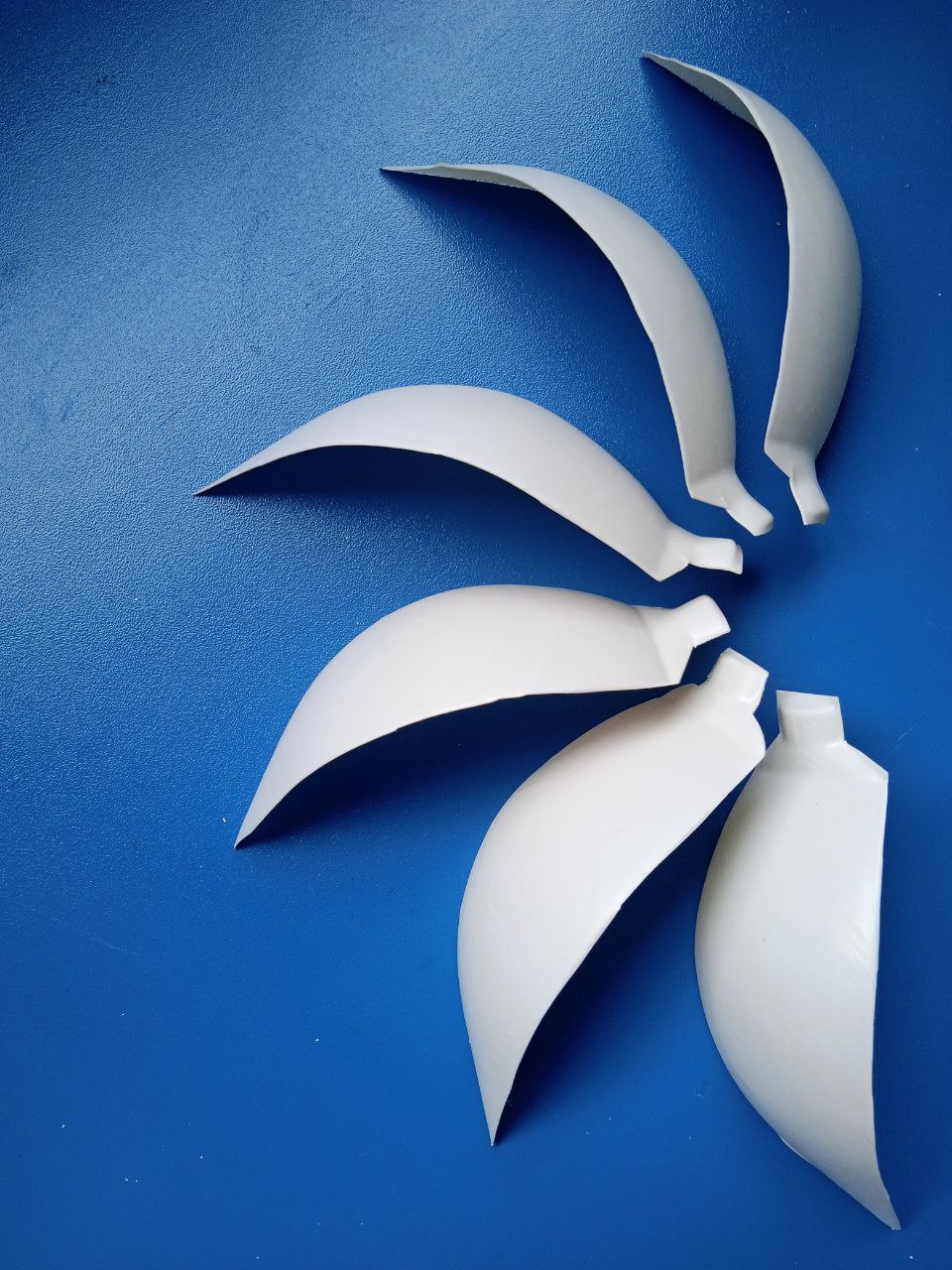
I needed to make petals for my final project. So I tried to make petals using vaccum forming in wild card week.
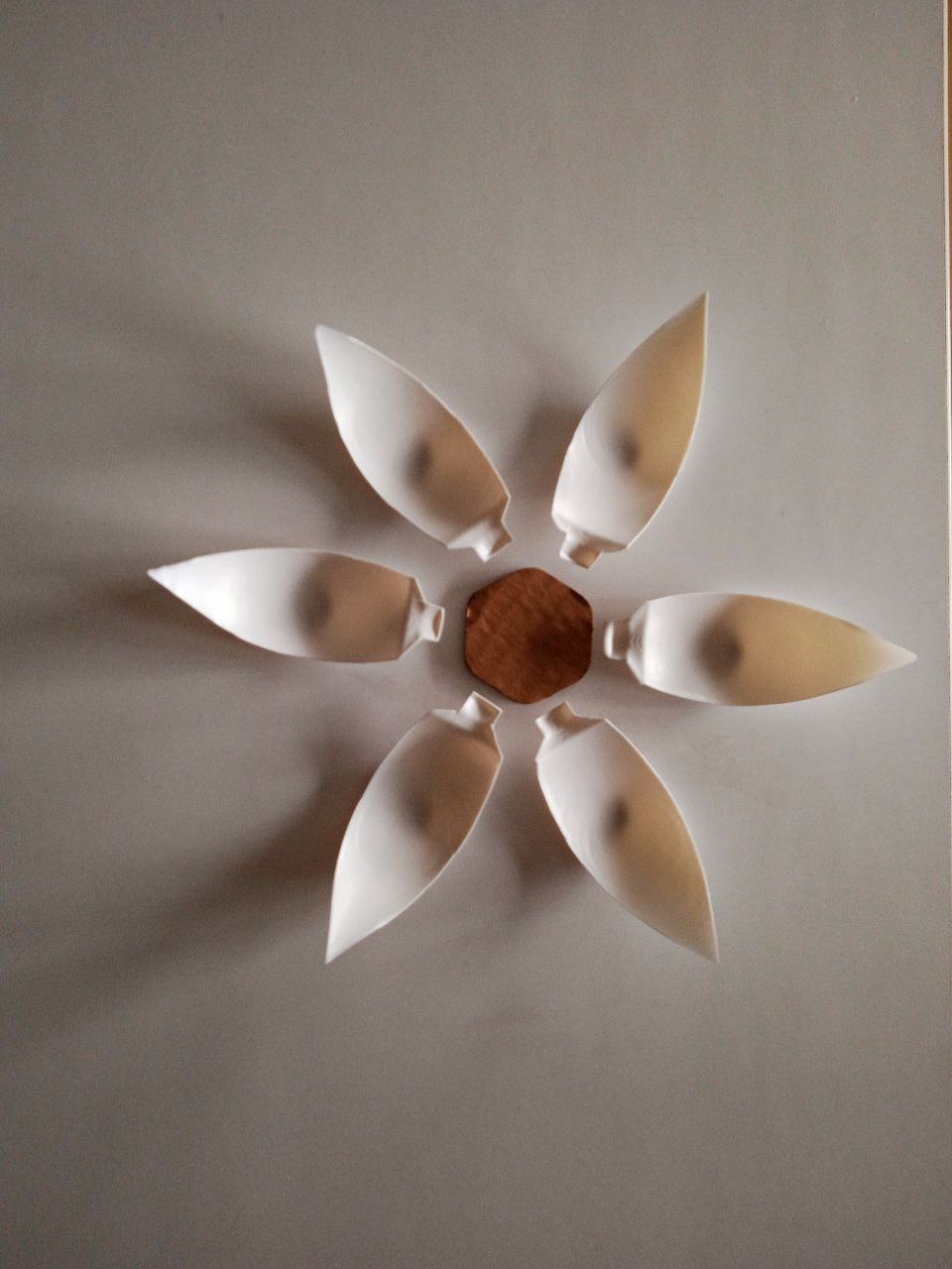
I lasercut the size of my cup and to visualize the petal arrangement
I tried to print the leafholder of my lamp and tested it
Testing the Concept
Testing the concept using vaccum formed petals
Schedule 1
The initial schedule was prepared during the Application and Implication, Project development week.
| TASKS | ESTIMATED DATE |
|---|---|
| BOM and schedule | April 26 |
| 3D model and render | April 31 |
| Mechanism design | May 6 |
| Electronics design | May 8 |
| PCB making | May 10 |
| 3D printing, wood cutting | May 15 |
| Assembling the parts | May 20 |
| Programming and testing | May 25 |
| Videos, photos and poster | May 30 |
| Final updations and completion of documentation | June 2 |
What tasks remain ?
The following tasks are still remaining for the completion of the project:
What's Working?
The system's individual components have been tested and are functioning as expected. The sensor reads distances accurately, ensuring reliable input data. The servo motor responds correctly to control signals, enabling precise mechanical movement. The LED brightness control operates as intended, providing smooth and responsive lighting adjustments. Additionally, the app interface successfully responds to user inputs, completing the interactive loop between hardware and software. Concept testing was conducted, and the mechanism worked smoothly, confirming the feasibility and effectiveness of the overall design.
What's Not Working?
Several aspects of the current design still need improvement. While the vacuum-formed petals are functional, their overall visual appeal is lacking. The leaf holder secures the petals well, but repeated disassembly and reassembly lead to deformation of the petals. The size of the cup is too large and needs to be reduced to improve the aesthetic balance. The servo mechanism lacks a proper pivot structure, which is necessary to manage angular motion and maintain stable up-and-down movement. A strong center shaft is also needed to support the moving parts and ensure structural stability. Additionally, the design needs to be more modular to facilitate easier assembly, testing, and future modifications.
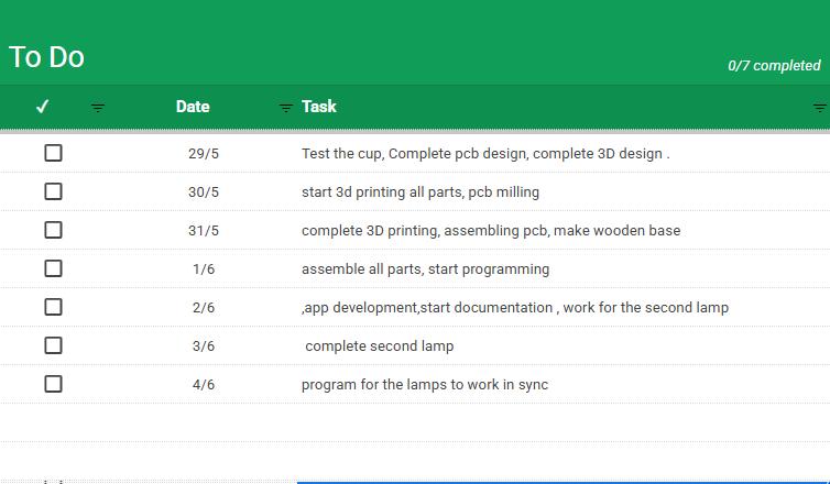
what will happen when?
The initial project timeline was ambitious, but due to the complexity of integrating mechanical, electronic, and software components, some tasks couldn't be completed as per the original schedule. Recognizing this, I created a revised task schedule using Excel's To Do list template to help me organize remaining milestones clearly.
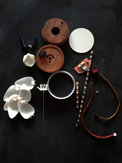
Final Project
CAD in Fusion 360
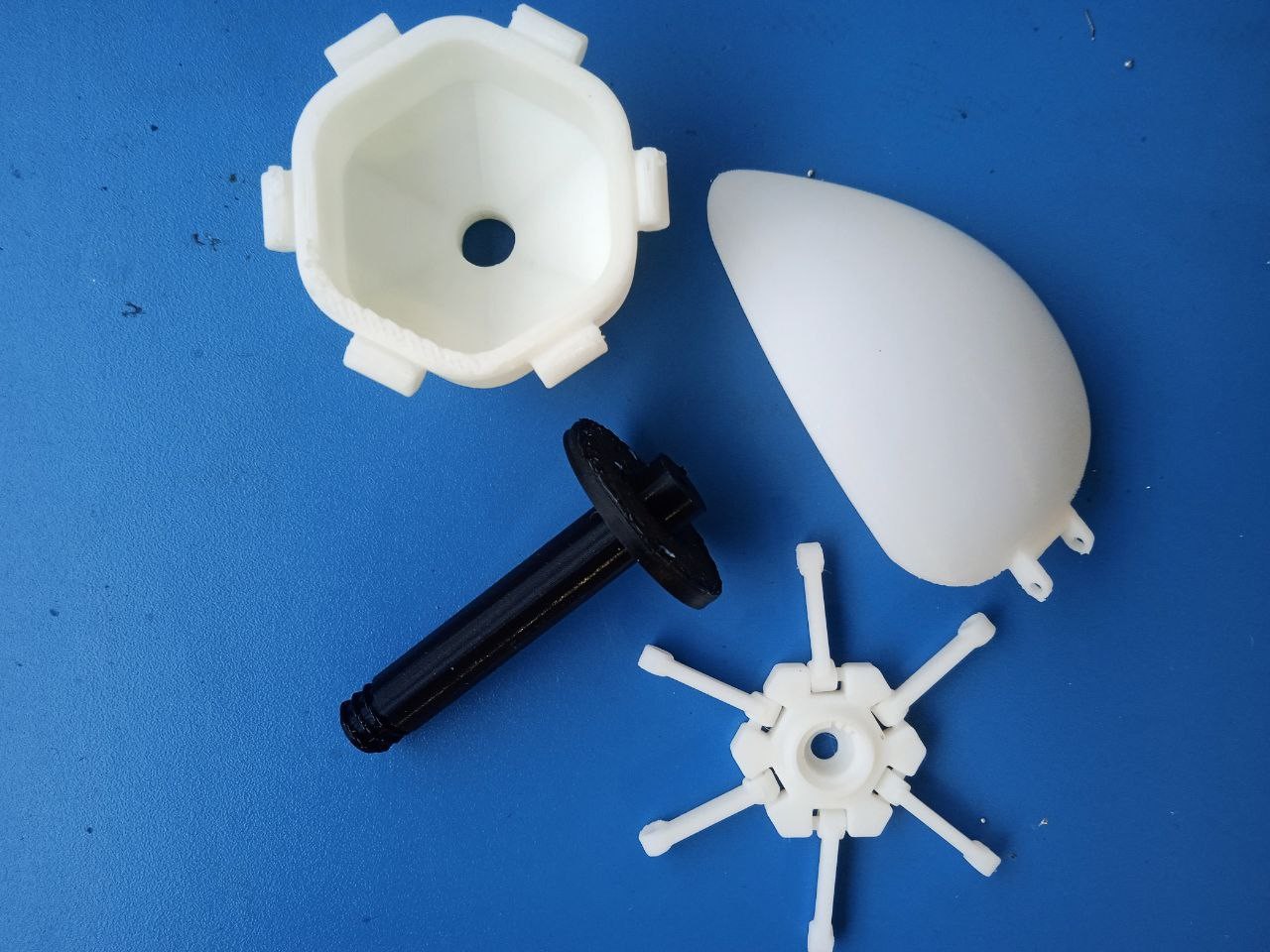
Cup, Outershaft and Linkage
Initially, I planned to design petal holders that would support vacuum-formed petals. The goal was to keep the structure lightweight and visually delicate. However, after experimenting with early forms, I realized that the result wasn't as aesthetically pleasing or mechanically reliable as I had hoped. The petals lacked the desired smooth curvature and structural stability. To improve both form and function, I decided to 3D print the petals instead. This gave me much greater control over the shape, thickness, and curvature, and allowed me to design them with built-in features like pivot holes and matching joints.Before committing to 3D printing, I wanted to test the blooming mechanism virtually. Following the instructor's advice, I created a CAD model of the essential moving parts: the inner cup, outer shaft, and linkages. Using Fusion 360's joint system, I simulated the motion to ensure smooth actuation and to identify the correct linkage lengths for the desired petal movement. This allowed me to tune the angular motion and check for potential collisions or binding, ensuring the mechanism would work reliably in the physical build.
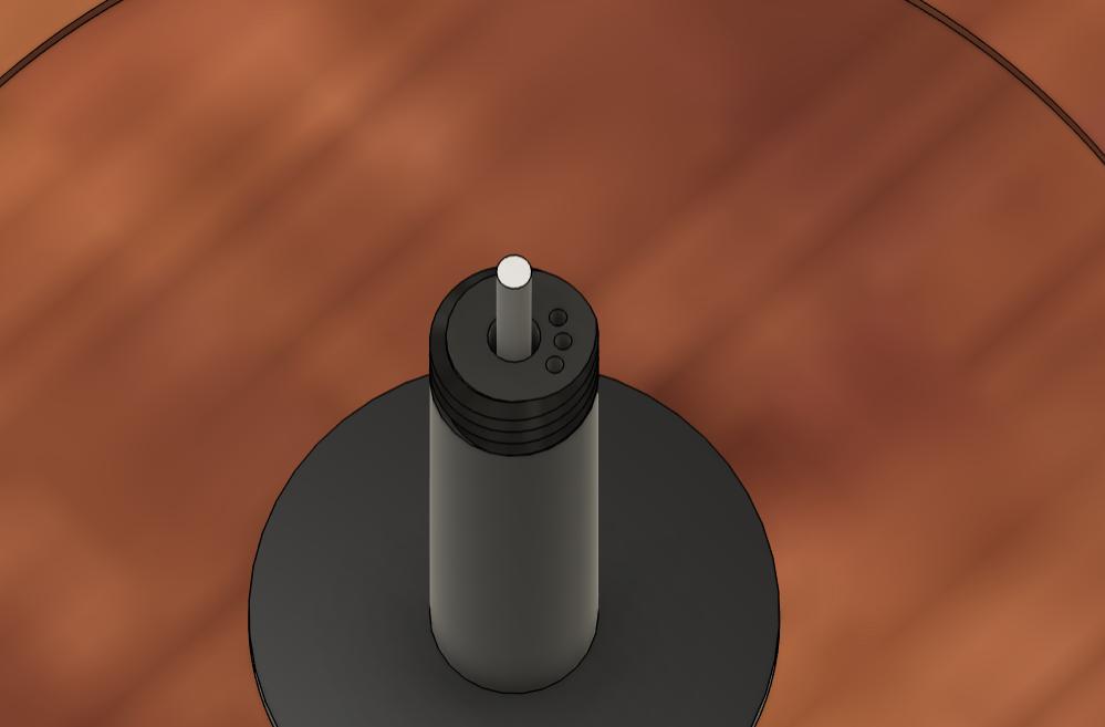
As the design evolved, I decided to remove the petal holders entirely and instead adjust the geometry of the cup to make the lamp more visually compact and cohesive. By reducing the cup size, the form gained a more elegant and minimal aesthetic while still supporting the blooming mechanism and diffusion function. I redesigned the petals, outer shaft, and cup as interrelated components. The stem was planned to press-fit into a wooden base, ensuring a stable foundation without the need for adhesives or fasteners. To support modularity, I incorporated a threaded joint between the stem and the cup. This allows the upper light assembly to be easily detached or replaced without affecting the base — ideal for future upgrades or repairs.
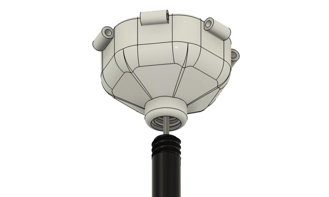
I also considered the electronics integration during the CAD phase. A dedicated space was included on top of the linkage to mount a NeoPixel, ensuring that the light would track the motion of the blooming petals.To maintain clean wire routing, I included 1 mm diameter holes in both the linkage and outer shaft. These act as channels for the Data In, 5 V, and GND wires, allowing them to pass neatly from the NeoPixel down to the base without interfering with mechanical movement.
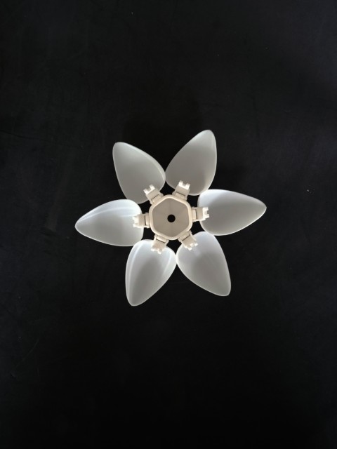
Petals
To create the petal shape, I began by drawing a spline around a 5 cm diameter circle, defining the petal’s flowing contour. Using the Sweep tool, this spline was swept along a central axis to generate a smooth, curved solid body. To mimic the natural behavior of flower petals, the solid was divided into four segments, each with a slight overlap. This subtle offset between adjacent petals enhances the realism of the bloom both when opening and closing, producing a more lifelike and layered appearance. After segmenting, I applied the Shell tool to give the petals a thin, uniform wall, and used the Chamfer tool to soften the edges, contributing to a delicate, organic look. Finally, each petal segment was combined with the original petal holder geometry to maintain consistent pivot distances and attachment points. This ensured mechanical compatibility with the rest of the blooming system while achieving the refined aesthetic I was aiming for.
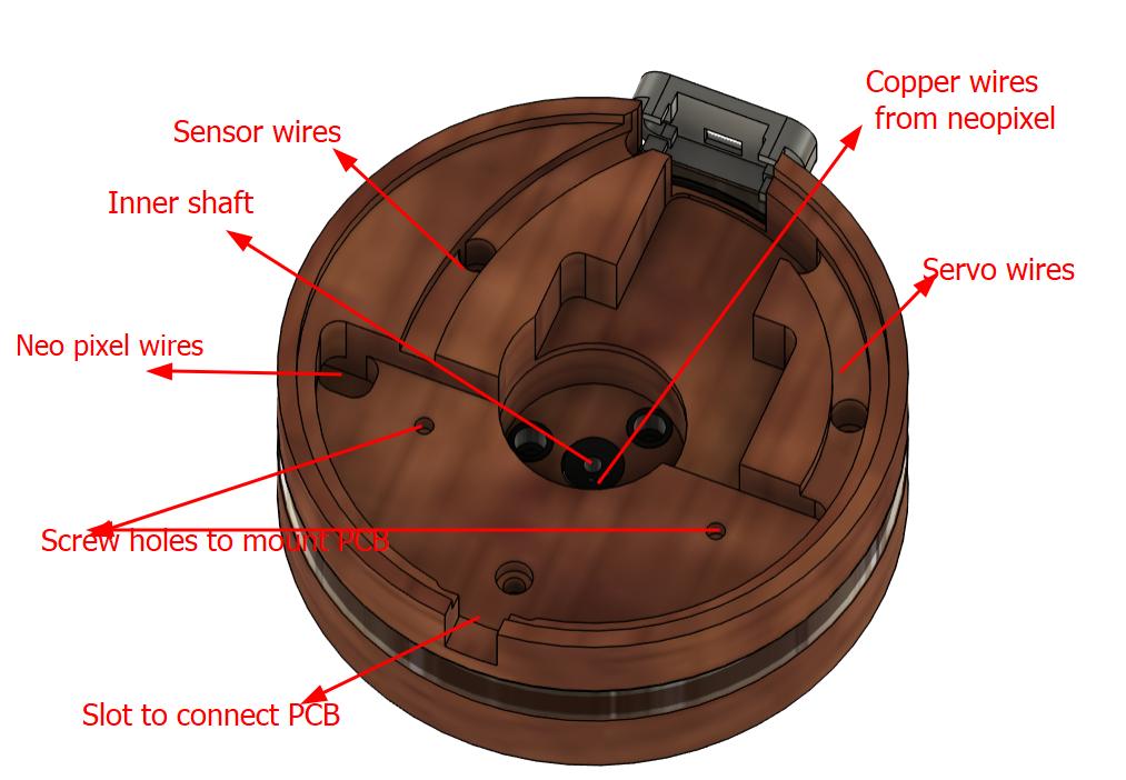
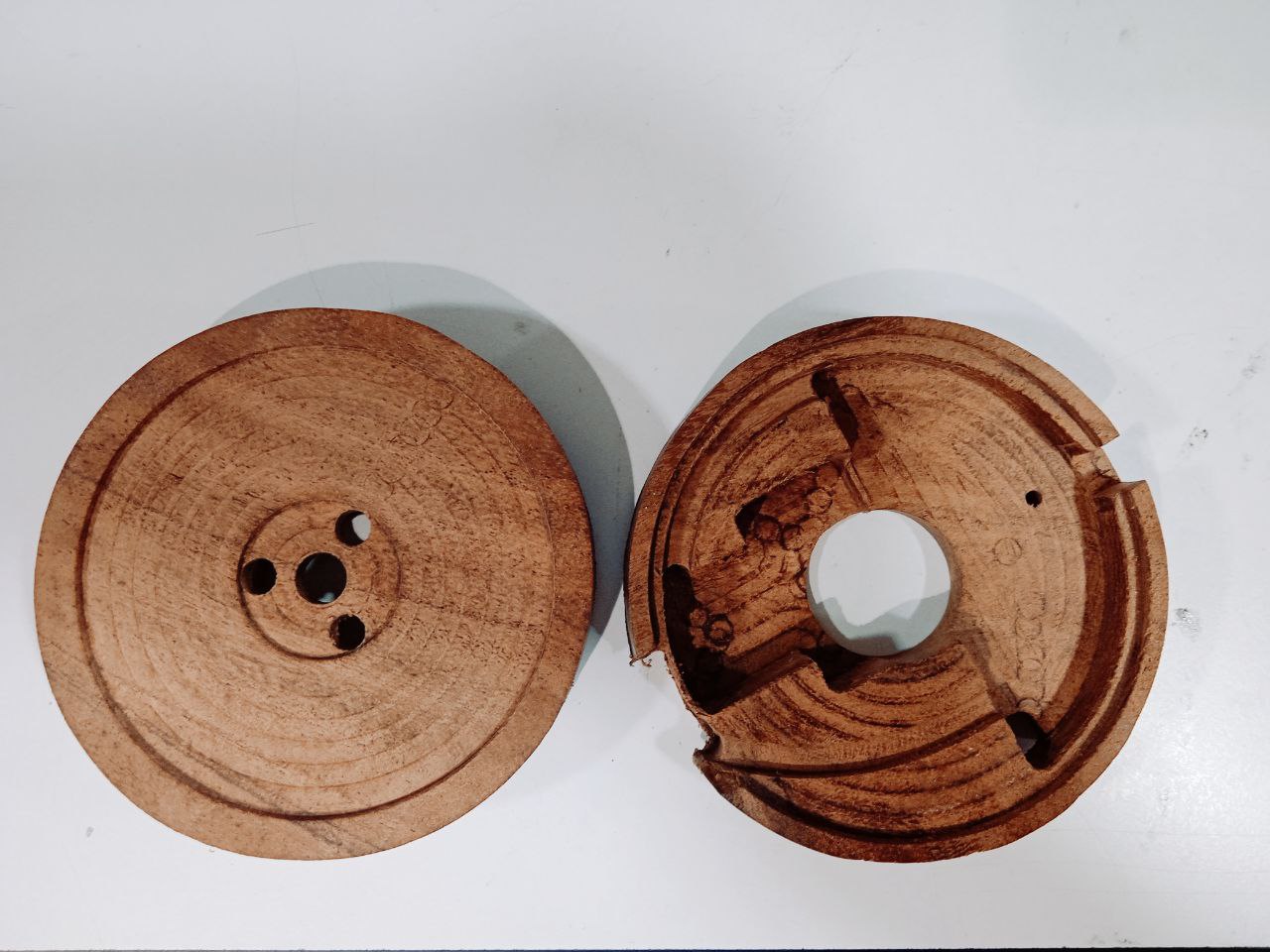
Base
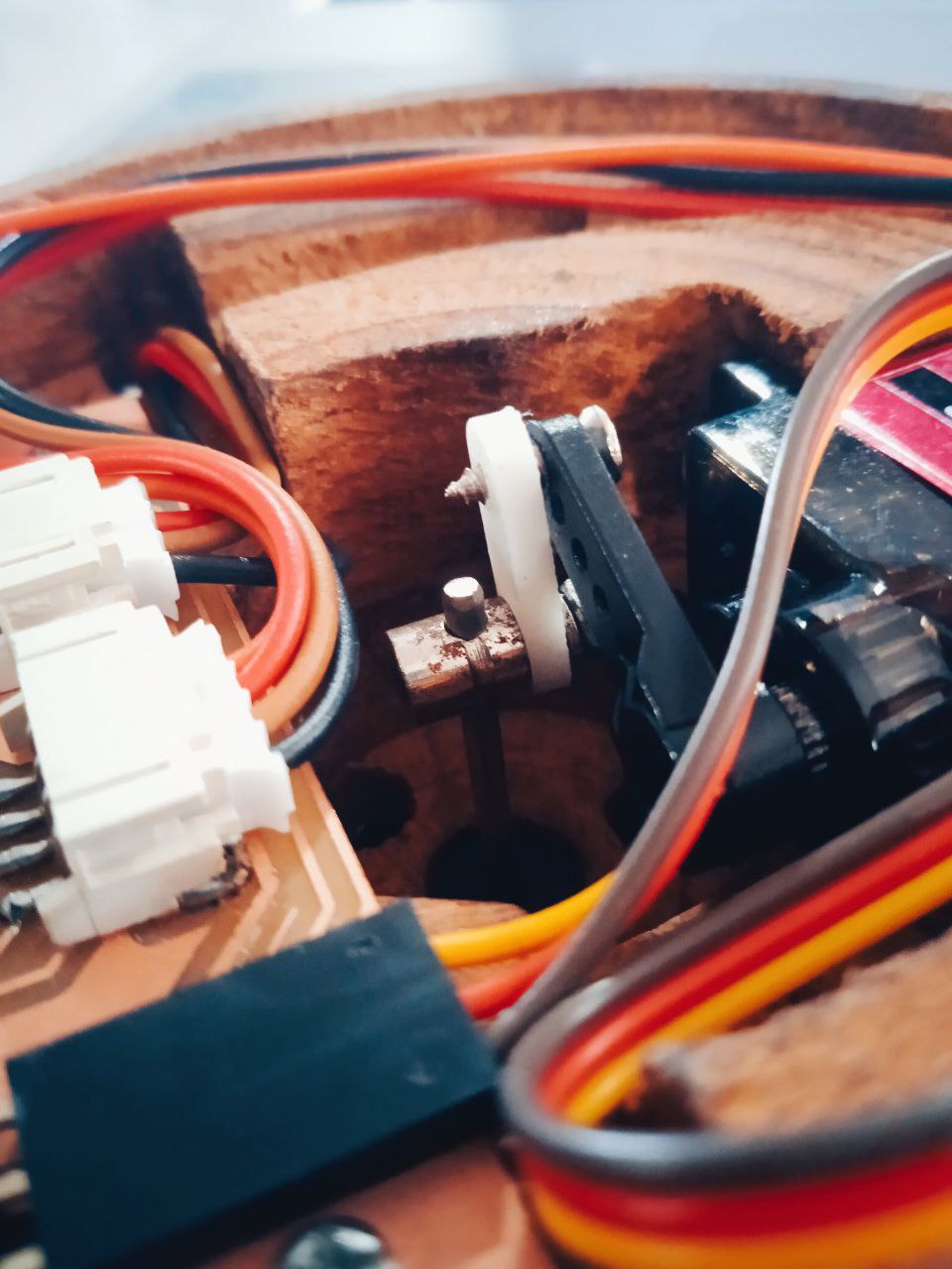
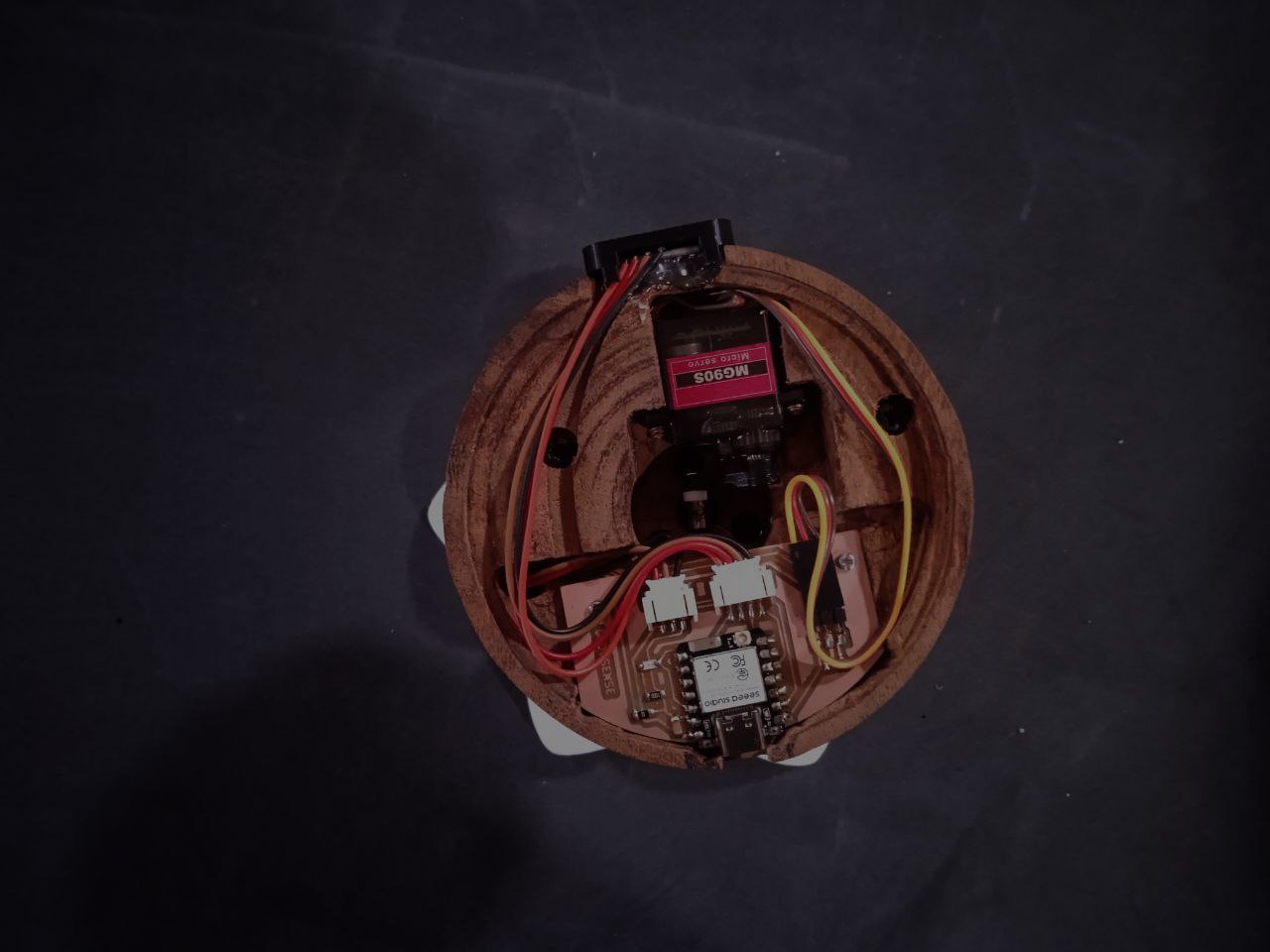
To neatly integrate the electronic and mechanical components, I focused on optimizing the wooden base. Following our instructor’s advice, the height of the base was adjusted to accommodate all internal components without crowding. A semicircular platform was created within the base to mount the PCB, with screw holes added to ensure a secure and stable fit. Just in front of this, a precisely dimensioned depression was carved to house the MG90S servo motor, keeping it firmly in place and aligned with the central axis of the mechanism. To organize the wiring, dedicated channels were modeled into the base to guide cables from the servo, NeoPixels, and distance sensor module down to the lower section — keeping the interior clean and free of entanglements.To maintain a clean appearance, I addressed the visible seam between the two stacked wooden base parts. Instead of leaving the joint exposed, I followed Saheen's suggestion and strategically placed a circular NeoPixel ring around the base at the point where the two layers meet.
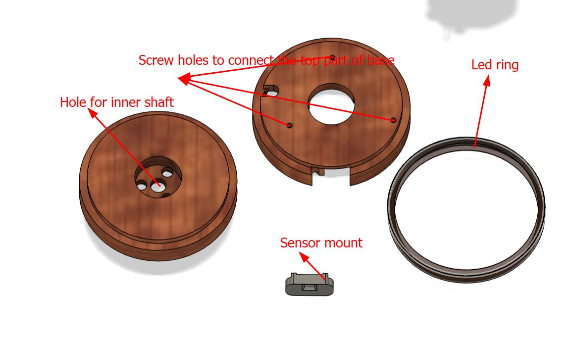
PCB, servo and sensor all are neatly placed and attaced to the base firmly.
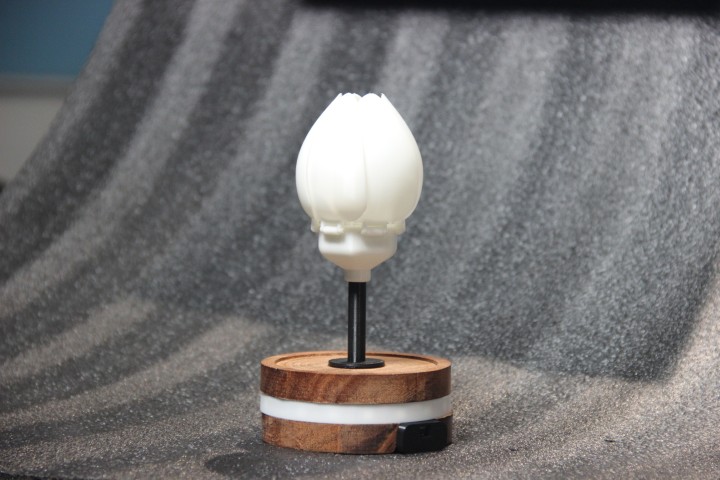
With all components carefully integrated — from the blooming mechanism and electronic layout to the modular base — the final assembly was completed. The result is shown below, demonstrating a fully functional and visually refined version of the GlowSense lamp.
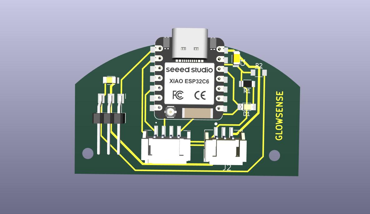
KiCAD
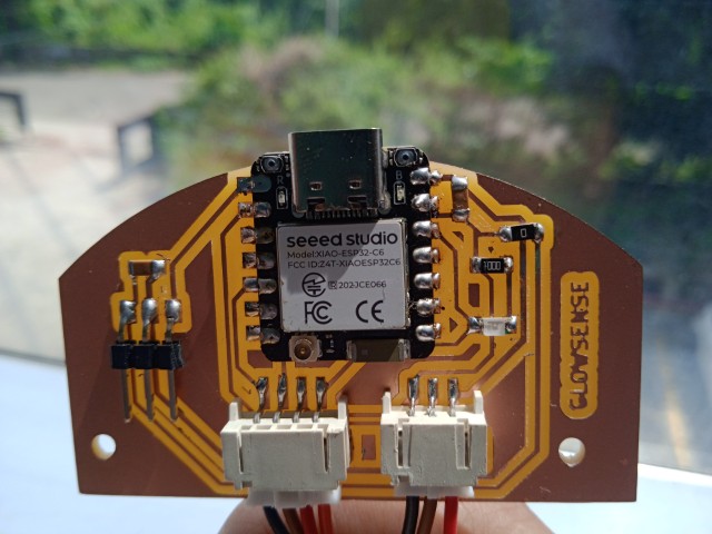
The custom PCB was designed using KiCad, centered around the XIAO ESP32-C6 microcontroller.
Key Components & Features
- Microcontroller:The XIAO ESP32-C6 serves as the core processing unit, offering compact form, Wi-Fi support
- Power LED Indicator:A red LED was connected to the 3.3 V power rail through a 100 Ω resistor to provide a visual power indicator.
- Sensor Module Connector:A 4-pin horizontal male JST connector was placed to interface with a sensor module. The pins are designated for VCC, GND, and two signal lines SDA/SCL
- NeoPixel Output:A 3-pin horizontal male JST connector was added to drive a NeoPixel LED. It provides 3.3 V, GND, and data
- Servo Header:A 3-pin horizontal pin header was included for connecting a servo motor, supplying VCC, GND, and PWM signal
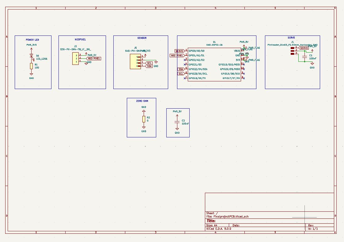
The board outline was created using an arc imported from Fusion 360, ensuring the edge cut matched the inner circumference of the project's base. This allowed the PCB to fit snugly and aesthetically into the enclosure, aligning mechanically with the rest of the design.
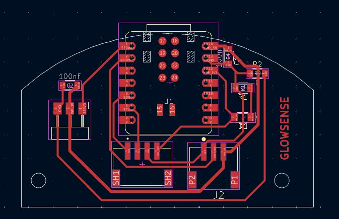
The 3D view of the PCB is shown below
Once the schematic and board layout were finalized, the project was exported as a set of Gerber files, ready for PCB fabrication.
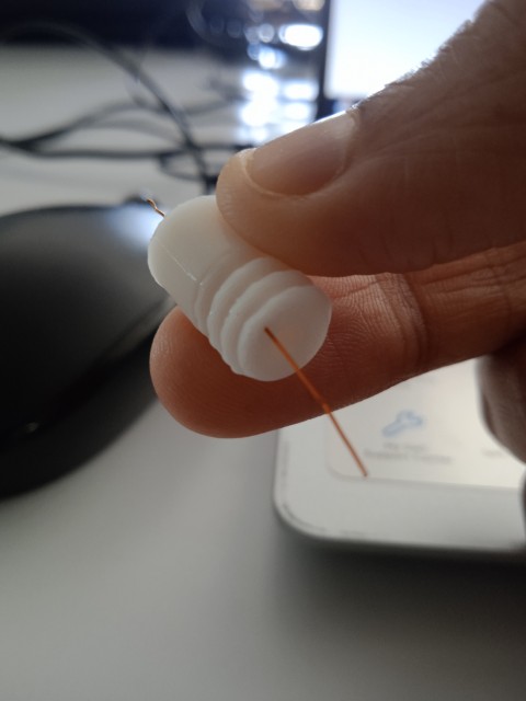
Testing
Testing thread
Testing holes for copper wires
Testing the mechanism
3D printing the parts
All 3D-printed components including the petals, cup and pivot body were fabricated using PLA filament on the Bambu Lab A1 and A1 Mini printers.
CNC milling
The wood was first cut to size using a cutting machine, bringing it to the desired base dimensions of 130 mm × 230 mm. This specific size adjustment was necessary to fit the piece into the TRAK for the next machining step.
Once properly sized, the excess thickness was removed using the TRAK, bringing the wood down from 30 mm to 20 mm.
The cutting was performed using a Zund digital cutting machine. A DXF file containing the base outline was prepared and exported from the CAD software. The CAM processing was done directly in Zund’s software, where the toolpath was generated and adjusted based on material type and thickness.
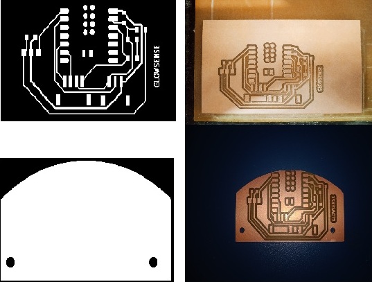
PCB milling
After designing the PCB in KiCad and exporting the Gerber files, the board was fabricated using subtractive milling. Gerber files were then converted into PNG format, suitable for use with the Mods CE workflow. Milling was carried out using the Modela MDX-20 3D Milling Machine.
The Mods CE was used to upload and process the PNG files and to generate toolpaths for both the traces (using 1/64" engraving bit) and the outline (using a 1/32" bit). After configuring parameters such as tool diameter, cut depth, and offsets, the milling job was executed.
Mechanical Parts
Linkage-stopper
Linkage stoppers are used to connect the pushrod to the servo and control horn (or directly to the control surface). They allow for fine-tuning the length of the pushrod after it's been installed
Bicycle spokes
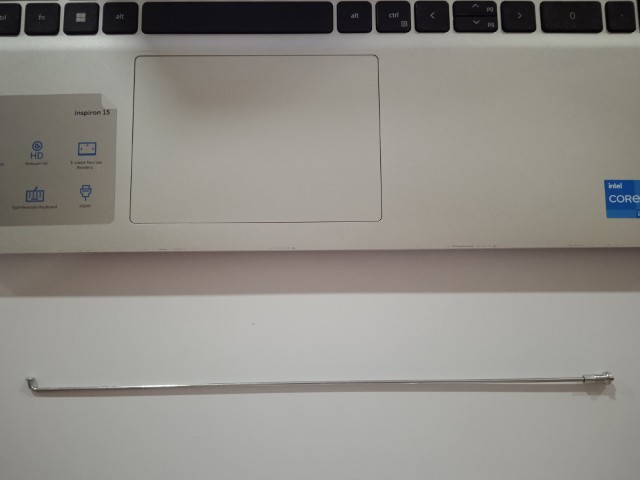
I used cycle spokes with a 2 mm diameter as pushrods for my linkage system. The spokes had threaded ends with caps, which I repurposed to attach the linkage. This setup made the connection between the pushrod and the linkage detachable, as they were joined through threading. Once I had adjusted the length to fit my mechanism, I simply cut off the excess spoke to keep everything neat and functional. This method gave me a strong, lightweight, and adjustable linkage without the need for specialized parts, and it worked reliably throughout the project.
Mechanical Jointing Using PLA Filament
To connect the linkages and petals in the assembly, small lengths of PLA filament were used as pins. These were inserted through aligned holes in the parts to act as mechanical fasteners. A soldering iron was then applied to both ends of each PLA pin, carefully melting and flattening them to form rivet-like heads. This technique effectively secured the parts together while maintaining rotational movement where required.
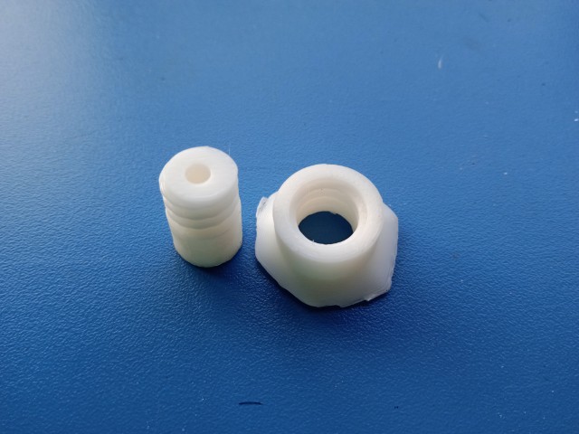
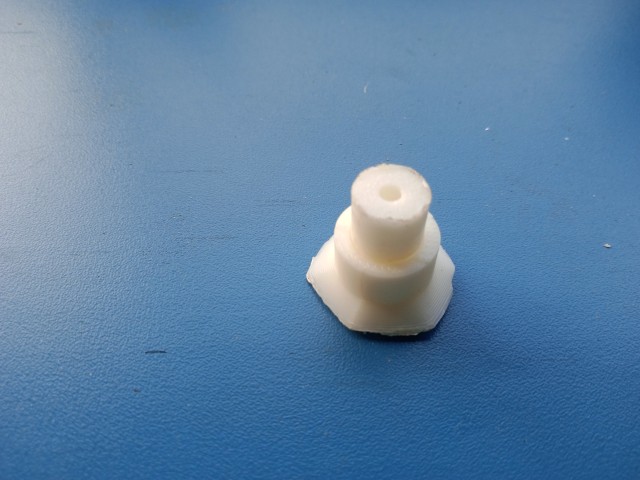
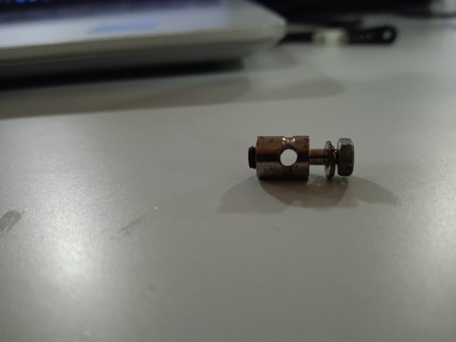
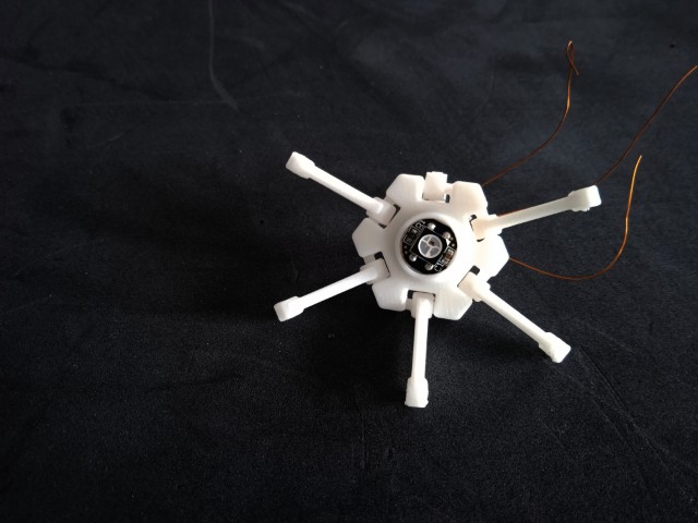
Pivot body
A pivot body was 3D printed to connect the servo horn to the linkage stopper. As the servo rotates, the pivot body compensates for the angular motion, ensuring smooth and controlled movement.The mechanism moves up and down, resulting in a smooth blooming and closing motion.
It was Saheen's suggestion to add these parts, and it considerably reduced both time and effort. The parts can be easily disassembled in case of maintenance
Assembly
PCB assembly
I requested the components through FabStash and collected them from the Fab Inventory.
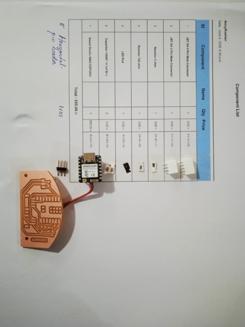
I then proceeded to solder the components.
The assembled PCB is shown below
ASSEMBLING the LAMP
I started by assembling the petals, then secured them using PLA filament, which was melted with a soldering iron to hold them in place.
I completed assembling the petals in the cup
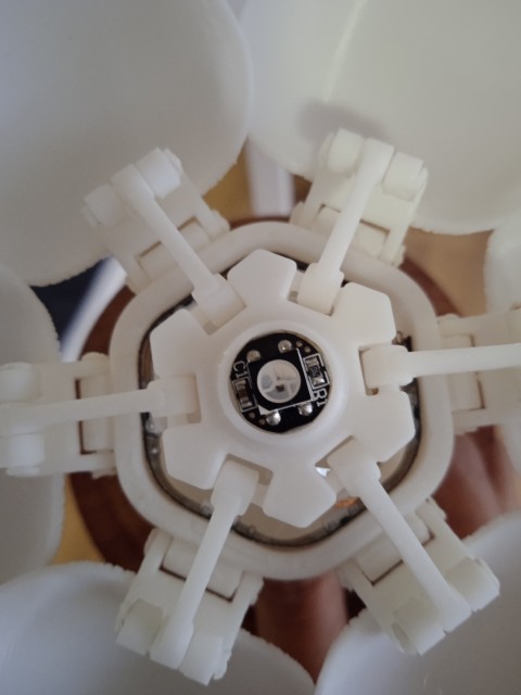
Next, I attached the head of the spoke and mounted the round NeoPixel onto the linkage.Three copper wires, connected to the round NeoPixel, were routed through the designated holes in the linkage.
After routing through the linkage, the three wires were connected to the NeoPixel strip.
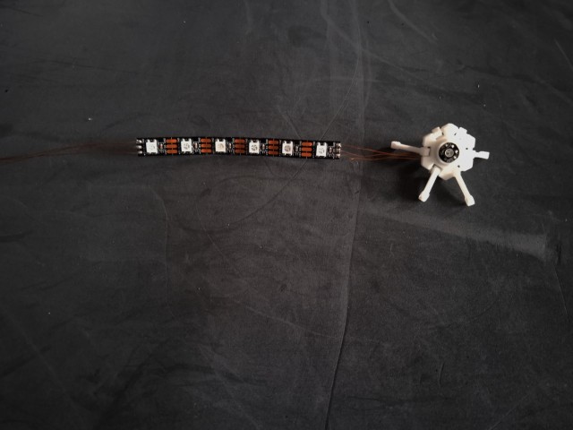
The strip is fixed inside the cup, and the linkages are connected to the petals. The three wires from the strip run down to the base through dedicated holes in the outershaft.
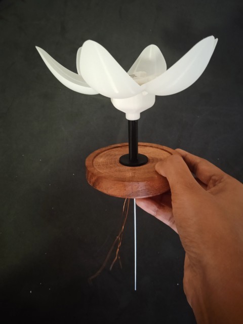
The inner shaft is secured using a threaded joint. The cup and outer shaft are also joined with a threaded connection. The assembled shaft is fixed into the wooden base as a press-fit. Any excess length of the inner shaft was trimmed off. Finally, the three wires were connected to the NeoPixel strip in the base
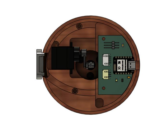
The NeoPixel strip was wrapped around the junction of the two base parts, along with the NeoPixel ring. Then, the second part of the base was joined to the first part using screws. I arranged the internal components within the base, and connected the NeoPixel strip to the PCB using a JST connector. The sensor mount had to be glued into the base, as a small section of the wood broke during milling. The sensor wire was also connected using a JST connector. The servo motor was connected to the PCB via a pin header. Finally, the PCB was secured inside the base using screws, and the servo was also mounted with screws.An acrylic base was cut using a laser cutter to enclose the bottom of the lamp base.
This is how the lamp looked after assembly
Fully closed
Half open
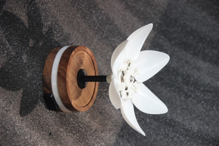
Fully opened
Programming
I used chatgpt to get the code. The prompt and response is included in the bottom part of the page.
#include <Wire.h>
#include <VL53L0X.h>
#include <Adafruit_NeoPixel.h>
#include <ESP32Servo.h>

#define LED_PIN 1
#define NUM_PIXELS 32
#define SERVO_PIN 0

VL53L0X sensor;
Adafruit_NeoPixel pixels(NUM_PIXELS, LED_PIN, NEO_GRB + NEO_KHZ800);
Servo myServo;

uint16_t rainbowOffset = 0;
int currentServoAngle = 0;  // Track current angle

void setup() {
  Wire.begin();
  Serial.begin(9600);

  pixels.begin();
  pixels.show();

  myServo.attach(SERVO_PIN, 500, 2400);
  myServo.write(0);  // Start at 0°
  currentServoAngle = 0;

  if (!sensor.init()) {
    Serial.println("VL53L0X Init Failed!");
    while (1);
  }

  sensor.setTimeout(500);
  sensor.startContinuous();
}

void loop() {
  uint16_t distance = sensor.readRangeContinuousMillimeters();

  if (sensor.timeoutOccurred()) {
    Serial.println("Timeout!");
  } else {
    Serial.print("Distance: ");
    Serial.print(distance / 10);
    Serial.println(" cm");
  }

  int targetAngle = (distance / 10 < 150) ? 155 : 85;

  // Smoothly move servo toward target
  if (currentServoAngle != targetAngle) {
    if (currentServoAngle < targetAngle) {
      currentServoAngle++;
    } else {
      currentServoAngle--;
    }
    myServo.write(currentServoAngle);
    delay(10);  // Adjust for slower/faster motion
  }

  // NeoPixel behavior
  if (distance / 10 < 150) {
    int brightness = map(distance / 10, 150, 0, 0, 255);
    brightness = constrain(brightness, 0, 255);

    for (int i = 0; i < NUM_PIXELS; i++) {
      int hue = (rainbowOffset + (i * 256 / NUM_PIXELS)) % 256;
      pixels.setPixelColor(i, pixels.gamma32(pixels.ColorHSV(hue * 256, 255, brightness)));
    }
    rainbowOffset++;
  } else {
    for (int i = 0; i  NUM_PIXELS; i++) {
      pixels.setPixelColor(i, 0);
    }
  }

  pixels.show();
  delay(20);  // Additional delay to smooth the loop
}
Developing an Application
During the Interface and Application Programming week, I developed a mobile app using kodular. The same interface was integrated into my flower-shaped mood lamp system. You can view the app and its development in the Interface and Application Programming week documentation
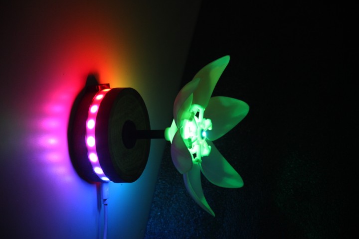
GLOWSENSE in Action
Creating Slide and Video
In application , Implication and project development week, I created a slide and video as a place holder for my final project.
Creating slide
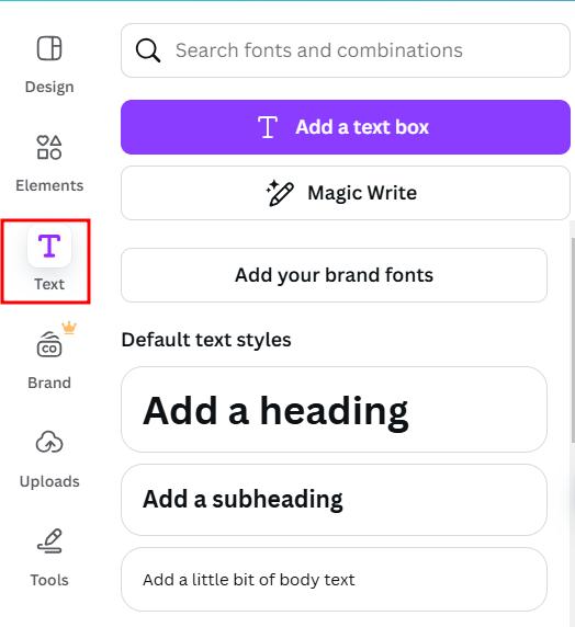
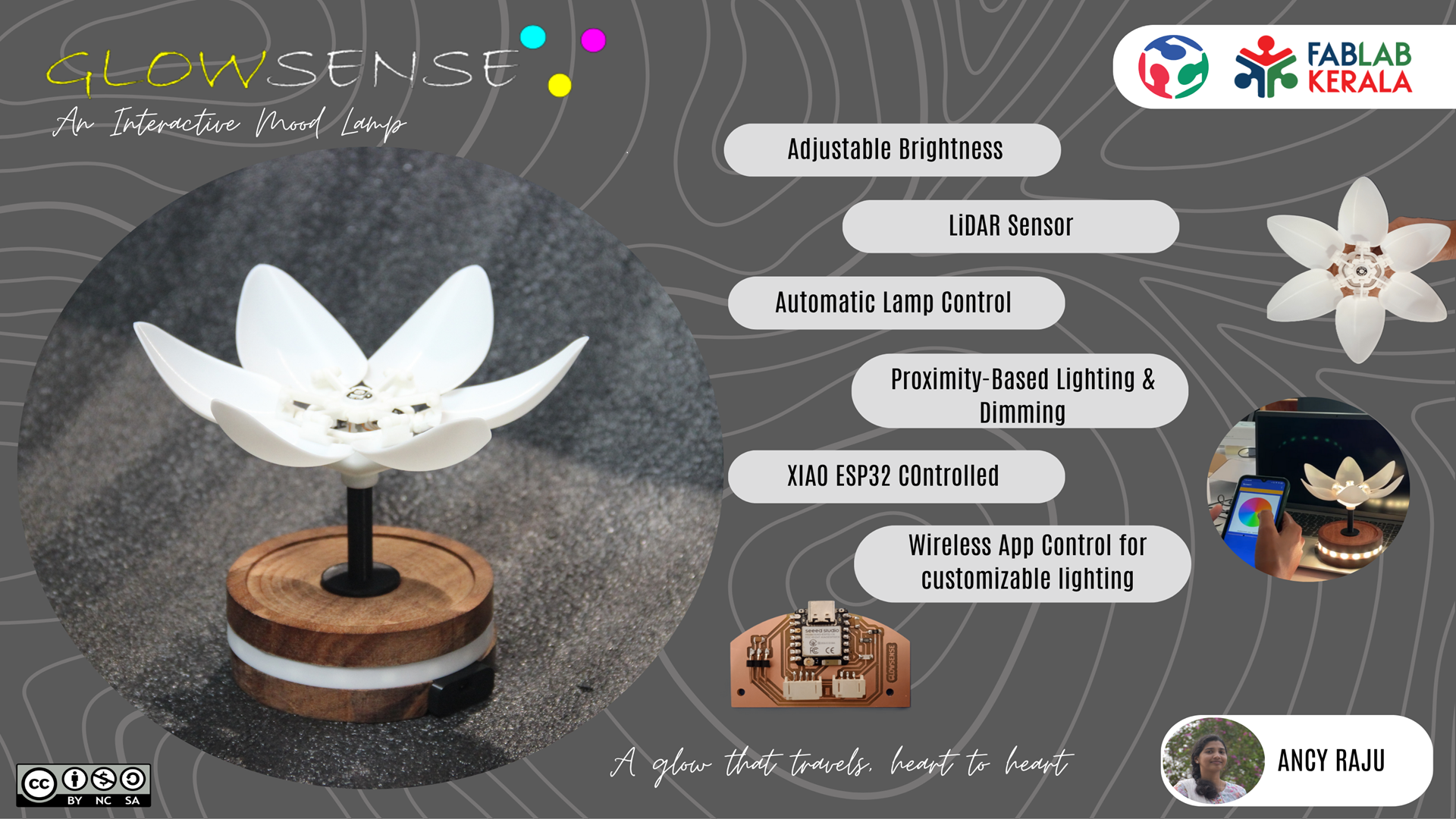
To create the slide ,I used Canva. Signin to canva and choose a templete. I chose a templete with black background. I uploaded my image after removing its background.

I used text box tool to write. From the element option, I selected buttons to write the features.

The slide is shown below. The size was 1366 x 768 px
 Presentation.png
Creating video
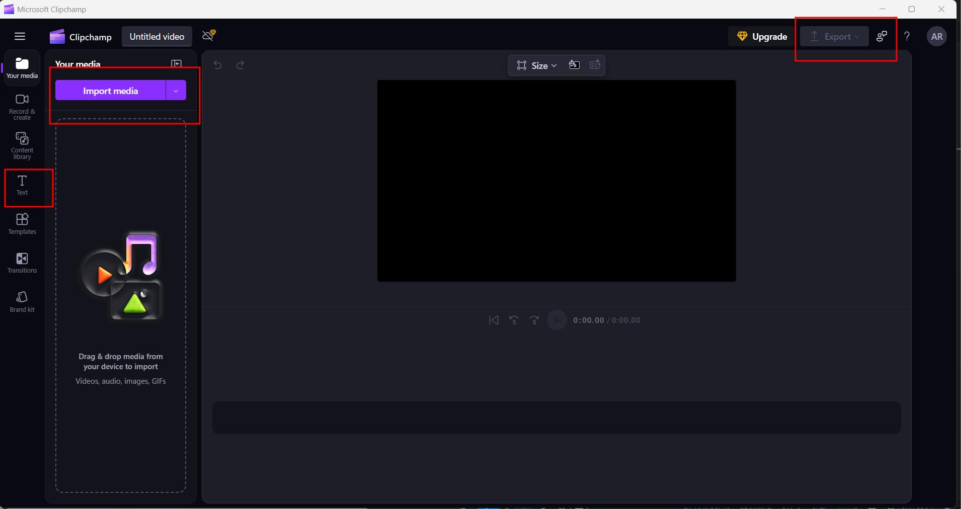
I used microsoft clipchamp to edit my video. I imported the media and drag and dropped the files to make the video. I used text option to add text. The video was exported and compressd to make the teaser video.
presentation.mp4
what I’ve learned?
Throughout the development of GlowSense, I gained valuable insights not just into technical aspects, but also in planning, iteration, and collaboration. Key lessons include:
-
Test Early, Test Often
Testing individual subsystems (sensors, servos, app interface, etc.) early on helped avoid complex debugging later during integration. -
Iterate Mechanically
Iterative prototyping of the linkages and holders using 3D printing allowed me to refine the design and catch mechanical issues before final assembly. -
Plan Realistically
Initial schedules were optimistic. I learned to plan with buffer time, because unexpected bugs and design changes are part of the process. -
Allow Time for Integration
Combining mechanical, electronic, and software components is not just additive—it’s a challenge in itself and needs dedicated time. -
Listen to Feedback
Suggestions from peers and instructors (like adding kinematics and wireless communication) had a huge impact on the evolution of my project. -
Let Ideas Grow
My project evolved significantly from a simple proximity lamp to a dynamic, wirelessly linked interactive flower. Being open to change made it better.
Files
CADfilesKiCADfiles
Program files
Prompt 1: Code with VL53L0X and LED brightness
VL53L0X code using LED brightness mapped to distance.
Prompt 2: Change it to a code for NeoPixel
Rewrote the code to use a single NeoPixel instead of analogWrite.
Prompt 3: Control multiple NeoPixels and add rainbow effect
Updated the code to control multiple NeoPixels and display a dynamic rainbow effect based on distance.
Prompt 4: Why I gave distance limit 50 and light glow only after 20
Explained that the map() logic and constraint only causes the LED to light when distance < 20. Suggested adjusting for 50 cm.
Prompt 6: Now I want a servo to work with it at the same distance limit in the same way as neopixel
Added servo control to match NeoPixel behavior when distance crosses a threshold.
Prompt 7: Servo library error on ESP32
The default Arduino Servo library does not support ESP32. Suggested installing the ESP32Servo library from the Library Manager.
Prompt 8: Servo moves in one direction after distance and opposite before
Implemented logic to rotate servo to different angles based on distance threshold.
Prompt 9: Can you decrease the speed of servo
Suggested using incremental stepping and delays to make the servo move more slowly.
Prompt 10: Give me all the prompt I gave you
Listed all your previous prompts and answers in a structured HTML format.